INTERNSHIP & ACADEMIC PROJECTS


Transonic Stall Flutter of Turbine Blades
Internship project focusing on research of stall flutter characteristics of turbine blade in cascade setup in transonic regime.
Test facility consists of a transonic wind tunnel with guide plates to push the air flow in desired direction and holding plates to sustain turbine blades in cascade setup. Experiments were conducted by performing blow-downs that were capable of producing a flow of Mach 1.3 at the test section. Turbine blades were initially kept without any external excitation. Experimental data was acquired through a PIV setup that consisted of a Photron Fastcam and a high intensity Nd-Yag laser. Acquired data was processed using Dantec Dynamics to obtain velocity field.
In addition to the PIV setup, several electronic transducers were placed along different locations inside the tunnel to obtain pressure measurements. Focus was to identify and isolate regions of excitation and damping. CFD cimulations were performed using FLUENT to compare the experimental results. Fast Fourier Transform (FFT) codes were written to process transducer signals using MATLAB.
My focus was on improving the accuracy of the pressure measurement by alleviating blockage inside the test section due to obstruction flow through holding plates. I was instrumental in redesigning both guide and holding plates by performing iterations in design based on feedback from pressure output.
Initial simulation on FLUENT indicated existence of strong shock structures between the blades which was confirmed by performing shadowgraphy. Based on the shock strength, the guide plates were redesigned to allow increased air flow by recalculating the number of holes, hole inclination and hole arrangement. My calculations helped redesign the plates which led to an improvement of 11% in pressure measurements. Standing shock structures were pushed to the far end of the test section and eventually were made to escape the test section without disturbing the flow.
Project | 01
Project | 02
Project | 03


Numerical simulation of elliptic flow through driven cavity
Program was written to solve two-dimensional unsteady Navier-Stokes equation for an elliptic flow inside a square cavity with moving wall at a given velocity. First order time and second order spatial differential schemes were used to discretize the equations. Explicit time discretization for convection and implicit scheme for diffusion were used. Additionally, Pressure-Poisson equation was used for determining pressure field without check-board splitting.
Different calculations were performed by varying parameters including flow Reynold's number, Grid spacing (intervals) and relaxation factors for SOR iterations.
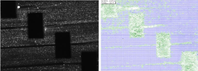
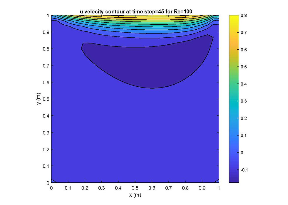
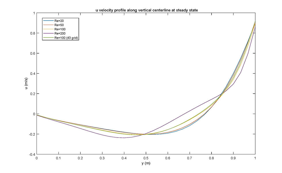
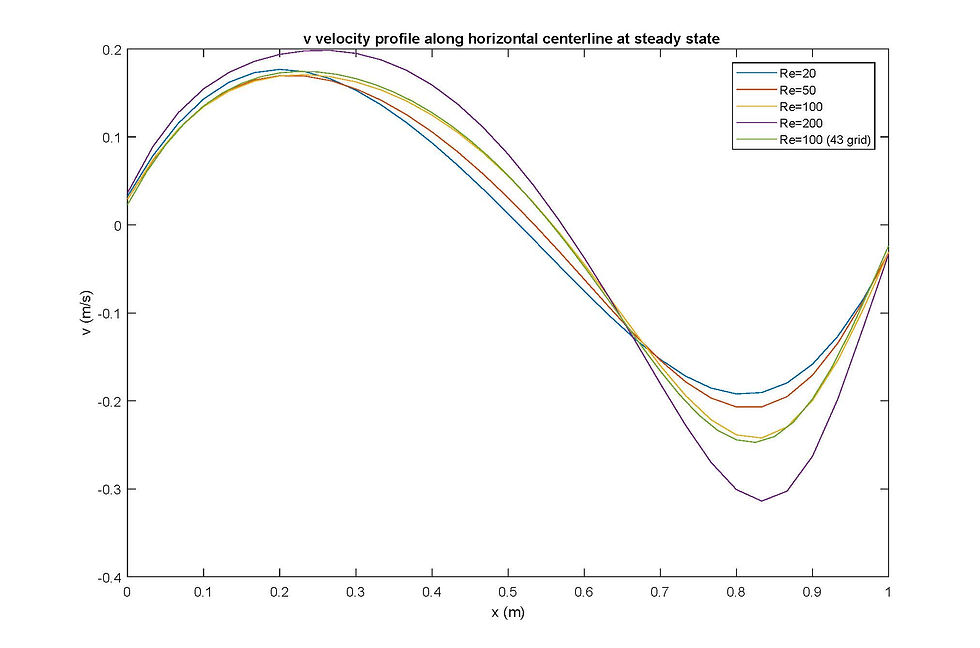
Images on the left show contours of horizontal and vertical velocity at different time intervals and at steady state along with streamlines at steady state. Velocity profiles are also shown for different Reynold's number. Results were used to compare the Moffat vortices for different Reynold's number and also the velocity resolution for different grid intervals.
The pictures on the left show velocity contours and streamline for Re = 50 and Re = 100. The movement of the moffat vortex towards the right side (same side as the top wall movement) for increasing Reynolds number through the streamline contour. This is used to study the impact of flow on the side walls. The velocity plots compares different Reynold's number at centerline location of cavity.
Heat Flow in Data Centers
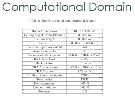
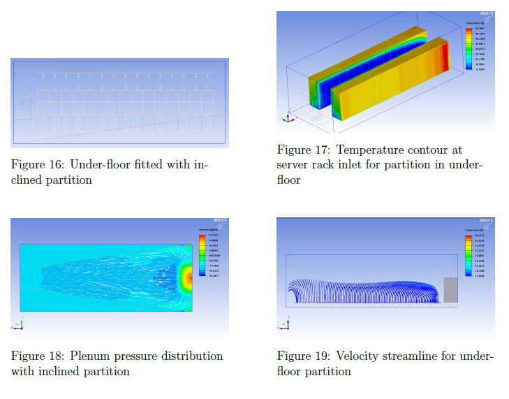
Aim was to study heat flow for raised floor data center model using numerical methods and simulations (ICEPAK). A base case was chosen with a single aisle of server racks and a single CRAC unit. Cooled air flows from the underfloor plenum through vents to the server racks on the aisle. The hot air exhaust is then directed to the CRAC unit which processes the air and supplied cooled air to the underfloor plenum.
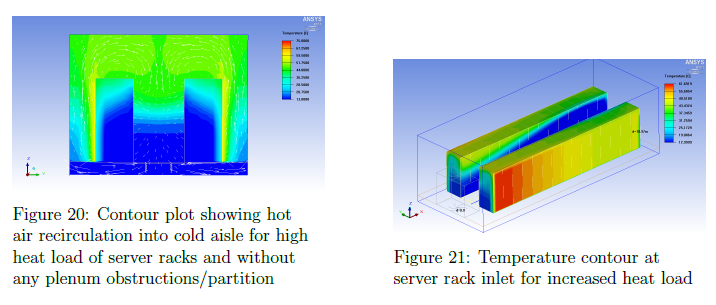
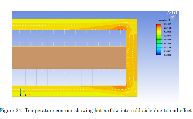
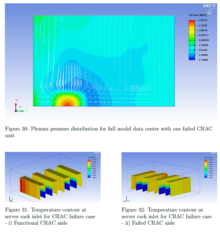
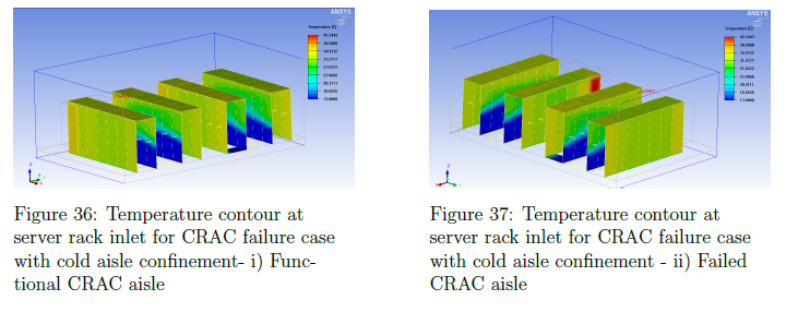
Variety of cases were studied including pressure distribution in plenum, geometry of perforated tiles, CRAC failure, hot air recirculation, end effect, aisle confinement, and support infrastructure.
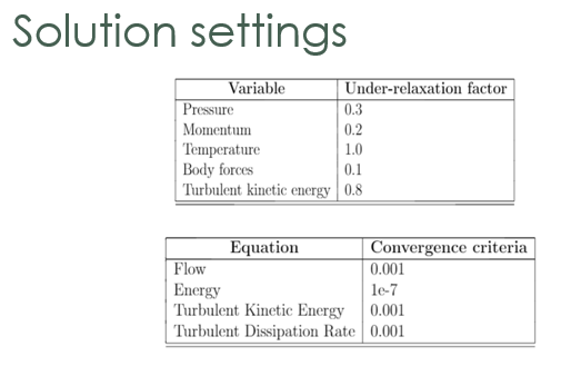
A base case was studied by picking a publication on ASHRAE. Solvers were setup on ICEPAK to reproduce the exact same results as the published results to verify and validate the solution solvers and setup that were being used. Once the validation was done, the base case was expanded to study for other cases. Information about the computational domain and solution setup is shown on the pictures.
A number of tests were run initially by varying the mesh resolution to identify the window of grid independence for solutions. A special case of CRAC failure for a multi-aisle data center model was performed for two conditions: a) design heat load and b) Bypass.
Numerical codes were written to model the temperature jump for flow through the server racks. The perforated tiles were also controlled to allow for increased airflow if a particular aisle had servers that were overheating.


Project | 04